What are asynchronous checks and why we need them
These are timing checks for asynchronous signals similar to the setup and hold checks. Enables recovery and removal timing model checks to be performed during timing analysis.
Recovery time is the minimum amount of time required between the release of an asynchronous signal from the active state to the next active clock edge.
Example: The time between the reset and clock transitions for a flip-flop. If the active edge occurs too soon after the release of the reset, the state of the flip-flop can be unknown.
Removal time specifies the minimum amount of time between an active clock edge and the release of an asynchronous control signal.

From another article
Recovery and removal checks are associated with deassertion of asynchronous reset. The assertion of reset causes the output to get reset and deassertion transfers the control of output to clock signal; i.e., deassertion of reset does not change the output.
However, to ensure that the design comes out of reset in deterministic cycle and to avoid metastability, there must be a region around arrival of clock edge within which reset must not be deasserted. This is similar to setup and hold timing checks, the difference being that:
Setup and hold checks are associated with synchronous data signals for a flop and are applied to both rise and fall transitions of data. Recovery and removal checks, on the other hand, are for asynchronous reset transitioning from active state to inactive state only (deassertion of reset).
To properly understand what recovery and removal checks are, we need to understand what asynchronous reset assertion and deassertion does.
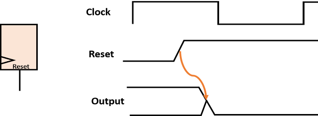
Asynchronous reset assertion: In a flip-flop, assertion of reset causes the output to go to its reset value (which is normally “0”). The assertion of reset is an asynchronous event and is not impacted by the state of clock. Figure 1 below depicts the assertion of reset. As it can be seen, Output asynchronously goes to “0” as an effect of reset going to its active state “1”.
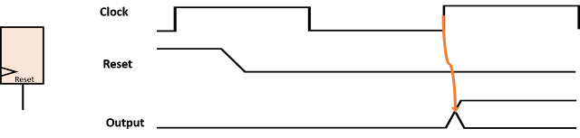
Asynchronous reset deassertion: The deassertion of asynchronous reset causes the output to get out of the impact of reset and behave like a normal flip-flop. When the reset gets deasserted, its output remains to be “0” until the clock edge. When the clock edge arrives, the value at the input of the flop propagates to the output. Figure 2 below depicts the same. However, the position of reset deassertion with respect to clock edge matters here as is the case with setup and hold checks. If the reset toggles in the vicinity of clock edge, the flip-flop may go metastable. This is avoided by defining recovery and removal checks for reset deassertion. For the sake of simplicity, we can say that recovery and removal checks are setup and hold checks for reset deassertion.
Reset recovery check: Recovery check ensures that the deasserted reset signal allows the clock signal to take control of the output at the desired clock edge. For this, reset signal must be stable at least “recovery time” before the active clock edge. Recovery time is the minimum time required between the deassertion of reset signal and arrival of clock edge. This can be modelled similarly as a setup check with the difference of it being a single sided synchronous check only.
Reset removal check: Removal check ensures that the deasserted reset signal does not get captured on the clock edge at which it is launched by reset synchronizer. For this, reset signal must be stable at lease “removal time” after the active clock edge. Removal time is the minimum time required between the arrival of clock edge and the deassertion of reset. This can be modelled similarly as a hold check with the difference of it being a single sisded synchronous check only.
Figure below shows reset de-assertion as a complete picture and summarises what we have discussed in this post.
