Clock Jitter
By definition, clock jitter is the deviation of a clock edge from its ideal position in time. Simply speaking, it is the inability of a clock source to produce a clock with clean edges. As the clock edge can arrive within a range, the difference between two successive clock edges will determine the instantaneous period for that cycle. So, clock jitter is of importance while talking about timing analysis. There are many causes of jitter including PLL loop noise, power supply ripples, thermal noise, crosstalk between signals etc. Let us elaborate the concept of clock jitter with the help of an example:
A clock source (say PLL) is supposed to provide a clock of frequency 10 MHz, amounting to a clock period of 100 ns. If it was an ideal clock source, the successive rising edges would come at 0 ns, 100 ns, 200 ns, 300 ns and so on. However, since, the PLL is a non-ideal clock source, it will have some uncertainty in producing edges. It may produce edges at 0 ns, 99.9 ns, 201 ns etc. Or we can say that the clock edge may come at any time between (

Please note that the uncertainty in clock edge can be for both positive as well as negative edges (above example showed only for positive edges). So, there are both full cycle and half cycle jitters. By convention, clock jitter implies full cycle clock jitter.
Types of clock jitter
Clock jitter can be measured in many forms depending upon the type of application. Clock jitter can be categorized into
- cycle-to-cycle.
- period jitter.
- long term jitter.
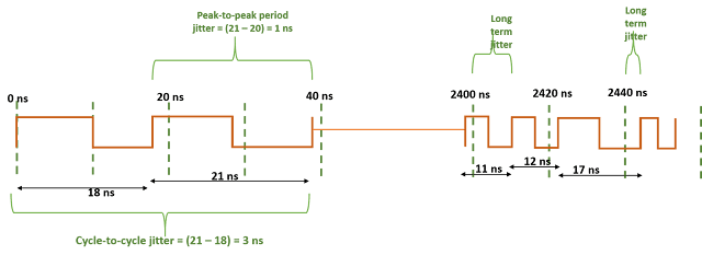
Cycle to cycle jitter By definition, cycle-to-cycle jitter signifies the change in clock period accross two consecutive cycles. For instance, it will be difference in periods for 1st and 2nd cycles, difference in periods for 10th and 11th cycles etc. It has nothing to do with frequency variation over time. For instance, in figure below, the clock has drifted in frequency (from period = 10 ns to period = 1 ns), still maintaining a cycle-to-cycle jitter of 0.1 ns. In other words, if t2 and t1 are successive clock periods, then cycle_to_cycle_jitter = (t2 - t1).
Period Jitter: It is defined as the “deviation of any clock period with respect to its mean period”. In other words, it is the difference between the ideal clock period and the actual clock period. Period jitter can be specified as either RMS period jitter or peak-to-peak period jitter.
Long term jitter: Long term jitter is the deviation of the clock edge from its ideal position. For instance, for a clock with period 20 ns, ideally, clock edges should arrive at 20 ns, 40 ns and so on. So, if 10th edge comes at 201 ns, we will say that the long term jitter for 10th edge is 1 ns. Similarly, 1000th edge will have a long term jitter of 0.5 ns if it arrives at 20000.5 ns.
Which type of jitter matters for timing slack calculation?
If we look into the equation of setup slack for a positive edge-triggered flip-flop to another positive edge-triggered flip-flop, we see that setup slack depends upon “clock period”. Now, if look closely, we will find that the clock period that we are talking about is actually distance between two clock edges. The larger the distance between the clock edges, greater will be the clock period. Hence, more positive will be setup slack.
Now, period jitter represents the absolute deviation of clock period from its ideal clock period. So, the jitter we should be looking for is maximum value of “peak-to-peak period jitter”. Peak-to-peak period jitter can either increase or decrease clock period. But, we need to take the effect of jitter to decrease clock period. This is because we have to take the worst case of clock period to have most pessimistic setup slack value. And the worst clock period will occur when peak-to-peak jitter is maximum.
So, we can say that for setup slack calculation, Clock period (actual) = Clock period (ideal) - peak-to-peak jitter (maximum)
What will happen to clock jitter for a multicycle path?
A multicycle path for setup of 2 will have a jitter of 2 times the peak-to-peak jitter of SOURCE_CLOCK, etc.
For single cycle paths, hold is on same edge. Hence, it is not effected by clock jitter.
When hold check is freq dependent (hold check is from N to (N-1) edge, hence, slack is affected by clock jitter. )
Can jitter in clock effect setup and hold violations?
In most simplistic language, jitter is the uncertainty of a clock source in production of clock edges. For example, if we say that there is a 100 MHz clock source. Ideally, it should produce a clock edge at 0 ns, 10 ns, 20 ns… So, if we say that there was a clock edge at time t = 30 ns, we should get the next clock edge at t = 40 ns. But this is hardly so; due to the uncertainty of getting a clock edge, we might get the next edge between 39.9 ns to 40.1 ns. So, we say that 0.1 ns is the jitter in the period of the clock. In reality, the definition of jitter is more complex. But, for our scope, this understanding is sufficient.
Let us consider a simple timing path from a positive edge-triggered flip-flop to a positive edge-triggered flip-flop.

Effect of clock jitter on setup slack for single cycle paths:
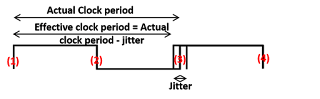
From our knowledge of STA basics, setup check formed, in this case, will be from edge 1 -> edge 3. Now, if we know that edge 1 arrived at 20 ns, then edge 3 may arrive at any time (20 ns + CLOCK_PERIOD + jitter) and (20 ns + CLOCK_PERIOD - jitter). So, to cover worst case timing scenario, we need to time as per (20 ns + CLOCK_PERIOD - jitter). So, effectively, we will get (CLOCK_PERIOD - jitter) as effective clock period.
In other words, jitter in clock period makes the setup timing more tight. Or it decreases setup slack for single cycle timing paths.
Effect of clock jitter on hold slack for single cycle paths: Going on the same grounds as setup slack, hold check will be from edge 1 -> edge 1 only. And we know with certainty that edge 1 will leave the source at 20 ns only. So, hold slack should not get bothered by the amount of jitter present at the clock source for single cycle timing paths.