Mutli bit flops and MIMCAP
Benefits of Multibit flops:
- Area reduction because of shared transistors and transistor level optimized layout: Area of Multibit cell is less than two single bit cells because of transistor level optimization of cell layout, which includes shared logic, power-supply and substrate-well.
- Total length of clock tree is reduced: This results in reduction of clock-tree buffers and clock-tree power. Clock-tree buffer level reduction improves overall balanced design skew.
- Power reduction.
- Better skew
Disadvantages of Multibit flops:
- Concentrated congestion spots sometimes increase due to the combined logic of multiple flops placed in limited area. It can be solved through optimization techniques like Cell padding, partial placement blockages, max density, skip tracks, etc.
- Formal checks are complex after multibit conversion.
- QoR of complex designs sometime degrades, requiring more optimization iterations.
- We have to experiment and see if multi bit works for a particular design, usually low performing designs show better PPA with multi bit and vice versa.
Why MIMCAP is needed?
The geometry scaling has led to thinner interconnects and reduced metal width. Interconnect lengths were also increased along with switching at gigahertz speeds to meet complex design requirement. The device scaling has increased the density of integrated transistors on the semiconductor wafer. There may be large current spikes due to simultaneous switching within short periods of time, which can cause the current resistance drop, voltage fluctuation and noise on the power supply network. These will affect reliability, speed and signal integrity. The addition of on-chip decoupling MIMCAP compensate voltage fluctuations by supplying charges to the power network. However, the capacitance must be large enough to meet the requirement.
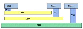
Where to Add?
MIMCAP cells are added to the blocks after power grid insertion. Decap cells are still required. MIMCAP doesn’t replace decaps, it rather adds to it. It is recommended to add these to places where there is little or no metal11 routing, since coupling to metal11 won’t be seen until extraction. It is recommended adding over high current density areas, such as TCAMs, high density or frequency logic areas, etc. There are placement rules regarding MIMCAP and die edge. Recommend >400u away from die edge.