Power Reduction Methods - Part2
Power switching is a power-saving technique in which portions of the chip are shut down completely during periods of inactivity.
Power switching has the potential to reduce overall power consumption substantially because it lowers leakage power as well as switching power. It also introduces some additional challenges, including the need for a power controller, a power-switching network, isolation cells, and retention registers.
PC- A power controller is a logic block that determines when to power down and power up a specific block. There is a certain amount of time and power cost for powering down and powering up a block, so the controller should determine the appropriate power-down times with a high degree of certainty.
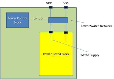

PSN- A block that can be powered down must receive its power through a power-switching network, consisting of a larger number of transistors with source-to-drain connections between the always-on power supply rail and the power pins of the cells. The power switches are distributed physically around or within the block. The network, when switched on, connects the power to the logic gates in the block. When switched off, the power supply is effectively disconnected from the logic gates in the block.
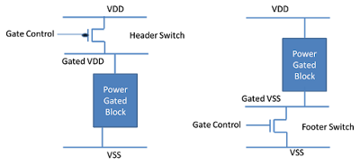
High-Vt transistors from a Multiple-Threshold CMOS (MTCMOS) technology are used for the power switches because they minimize leakage and their switching speed is not critical. PMOS header switches can be placed between VDD and the block power supply pins, or NMOS footer switches can be placed between VSS and the block ground pins, as shown in below figure. The number, drive strength, and placement of switches should be chosen to give in an acceptable voltage drop during peak power usage in the block.
Isolation Cells - Any use of power switching requires isolation cells where signals leave a powered-down block and enter a block that is always on (or currently powered up). An isolation cell provides a known, constant logic value to an always-on block when the power-down block has no power, thereby preventing unknown or intermediate values that could cause crowbar currents.
One simple implementation of an isolation cell is When the block on the left is powered up, the signal P_UP is high and the output signal passes through the isolation cell unchanged (except for a gate delay). When the block on the left is powered down, P_UP is low, holding the signal constant at logic 0 going into the always-on block. Other types of isolation cells can hold a logic 1 rather than 0, or can hold the signal value latched at the time of the power-down event. Isolation cells must themselves have power during block power-down periods.
Enable Level Shifter - The power switching can be combined with multivoltage operation. Different blocks can be designed to operate at different voltages and also to be separately powered down when they are not needed. In that case, the interface cells between different blocks must perform both level shifting and isolation functions, depending on whether the two blocks are operating at different voltages or one is shut down. A cell that performs both functions is called an enable level shifter. This cell must have two separate power supplies, just like any other level shifter.
Retention Registers - A retention register can retain data during power-down by saving the data into a shadow register (also known as the bubble register) prior to power-down. Upon power-up, it restores the data from the shadow register to the main register. The shadow register has an always-on power supply, but it is constructed with high-Vt transistors to minimize leakage during the power-down period. The main register is built with fast but leaky low-Vt transistors.