What is virtual clock and when to use it?
A virtual clock is a clock that exists but is not associated with any pin or port of the design. It is used as a reference in timing analysis to specify the input and output delays relative to a clock.
The following is an example where virtual clock is applicable:
The design under analysis gets its clock from CLK_CORE, but the clock driving the input port CORE_IN is CLK1.
To handle such cases, a virtual clock can be defined with no specification of the source port or pin. In the example (diagram), the virtual clock is defined for CLK1 and CLK2.
Having defined these virtual clocks, the IO constraints can be specified relative to this virtual clock.
from another article
purpose of defining a virtual clock
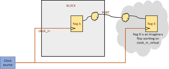
The advantage of defining a virtual clock is that we can specify desired latency for virtual clock. As mentioned above, virtual clock is used to time interface paths. Figure 1 shows a scenario where it helps to define a virtual clock. Reg-A is flop inside block that is sending data through PORT outside the block. Since, it is a synchronous signal, we can assume it to be captured by a flop (Reg-B) sitting outside the block. Now, within the block, the path to PORT can be timed by specifying output delay for this port with a clock synchronous to clock_in. We can specify a delay with respect to clock_in itself, but there lies the difficulty of specifying the clock latency. If we specify the latency for clock_in, it will be applied to Reg-A also.
Applying output delay with respect to a real clock causes input ports to get relaxed and output ports to get tightened after clock tree has been built. Let us elaborate it in some detail below. Let us assume clock period to be 10 ns and the budget allocated to be 3 ns inside; thus, having a “set_output_delay” of 7 ns.
Case 1: Applying “set_output_delay” with respect to real clock (R_CLK)
Pre-CTS scenario: Here, if we apply any latency to the clock, it will be applied both to launch as well as capture registers (capture register is imaginary here). So, we unltimately get a full cycle to time the path. In other words, applying or not applying a latency to the clock will time the path as needed.
Post-CTS Scenario Post-CTS, we need to “set_propagate_clock RCLK” in order for clock latencies to come into effect. Doing so, the launch register’s actual clock latency will come into picture. However, since, capture register is imaginary, there is no clock built onto it and its latency will be zero. So, we get (clock_period - RCLK_latency) as the actual phase shift to time the path. Thus, timing path gets tightened by “RCLK_latency”.
Case 2: Applying set_output_delay with respect to virtual clock (VCLK)
Pre-CTS Scenario In this case, in order to provide full cycle for the path to be timed; if we have applied any latency to RCLK, we will have to apply the same latency for VCLK as well.
POST-CTS scenario After CTS is built and clocks are propagated, network latency of RCLK will be overridden by actual latency. But VCLK will not be propagated and its source + network latencies will still be reflected as applied in constraints. If (VCLK_source_latency + VCLK_network_latency_user) is equal to (RCLK_source_latency + RCLK_network_latency_CTS), we will still see the same timing path as we see pre-CTS.
That is why we will have update_io_latency in our designs in CTS stage to match the vclk latency with real clock latency.